1.4 Install and configure expansion cards.
In general, you will follow these steps to install an expansion card in your PC:
If you're not using a PnP-compatible expansion card or operating system, determine the available system resources (IRQs, I/O addresses, and so forth). Configure the DIP switches or jumpers on the card, as necessary, to assign it available system resources.
If you're using a PnP-compatible card and operating system, the vendor might direct you to run an installation utility before installing the device. This installation program puts the necessary drivers in a location where Windows can find them when you're done installing the device. If appropriate, run that setup program now.
Shut down your PC, unplug it, remove peripheral cables, and open the case.
Locate an empty and available expansion slot of the correct type.
Remove the slot cover for that slot. These covers are generally either screwed in place or held by spring-clips.
If necessary, temporarily move or remove wires or other expansion cards that are in the way so that you can access the slot.
If you need to connect wire assemblies to the expansion board - not to its back slot cover plate, but to the board itself - connect that end of the wire assembly before installing the card. In this way, you can easily reach the connector and be sure you're installing the wire assembly in its correct orientation. Connect the other end after you have installed the card.
Begin inserting the end of the edge connector that's farthest from the slot cover. Then, gently push the card into place in the slot. This will help you line up the connector correctly. Inserting the card at an angle like this is usually easier than pushing it straight into the slot.
Fix the card in place with screws or clips, as appropriate to your case design.
Connect any wiring assemblies, including those you temporarily removed to install this card. Close the case, connect peripherals, and start the system.
Depending on your operating system, version, and adapter card technology, configure the card. If you're using PnP-compatible components, PnP will handle this for you.
If necessary, install required drivers. If you have to install drivers yourself, you will most likely need to configure them to use same hardware resources you configured the card to use.
When you're done, some devices and operating system versions will also require you to restart your computer. This fully loads the drivers and configures the operating system to support the new device.
1.5 Install and configure storage devices and use appropriate media.
Firewire : A standard FireWire connection will support 100,200 and 400 Mbps. The important features of IEEE1394 (also known as FireWire 400) are:
100 Mbit/s, 200Mbit/s, and 400Mbit/s supported.
Works without control, devices communicate peer-to-peer.
Cable up to 4.5 m.
Up to 63 devices supported.
Power supply to external devices is 1.25A/12V (max.).
The only computer bus used in digital video cameras
USB (Universal Serial Bus):
a. USB supports up to 127 devices simultaneously.
b. USB enables you to daisy chain up to 127 USB devices. A USB hub is used for this purpose.
c. USB devices can be plugged in without turning on/off power. i.e, USB devices are hot swappable.
d. The important features of USB 2.0 are given below:
Mbit/s 12Mbit/s 480Mbit/s supported.
USB controller is required to control the bus and data transfer.
Cable up to 5 m.
Up to 127 devices supported.
Power supply to external devices is 500 mA/5V (max).
Full compatibility with USB 1.1 devices.
e. To achieve proper USB connectivity six basic system elements must be present:
Support from the BIOS
Support from the Operating System
Physical USB ports
A USB Device
The correct USB cable for the device
Drivers either from the OS and/or the peripheral maker
f. USB 2.0 has a raw data rate at 480Mbps, and it is rated 40 times faster than its predecessor interface, USB 1.1, which has 12Mbps max speed.

USB Type A

USB Type B

USB mini Type A

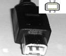
USB mini Type B
eSATA
a. External Serial Advanced Technology Attachment or eSATA is an external interface for SATA technologies. It is faster compared to USB 2.0 or PATA technologies, and suitable for backing up large amounts of data using external hard drive
b. Even though eSATA is part of the SATA interface specifications, it uses a very different physical connector from the internal SATA connectors. The reason for this is to better shield the high speed serial lines used to transfer the signals from EMI protection. It also provides a 2m overall cable length compared to the 1m for internal cables. As a result the, the two cable types can not be used interchangeably.
c. eSATA is hot swappable. Other drives IDE, EIDE, AND PATA does not support hot swap.

Blue-ray
a. Storage capacity of blue-ray: 25GB (single-layer) and 50GB (dual-layer)
b. Blue-ray drives are usually compatible with CD/DVD drives, but not the other way round.
Copyright © Anand Software and Training Private Limited.